
Plants are able to sense their mechanical environment. For example, leaves of touch-sensitive plants, such as mimosa (Mimosa pudica) and Venus flytrap (Dionaea muscipula), rapidly fold and bend in response to stimulation or close to catch a prey, respectively. This is true also at a smaller scale. Morphogenesis, both at the cell and tissue level, involves mechanical signals that influence specific patterns of gene expression and trigger cytoskeletal reorganizations. How mechanical stress is perceived and how this signal is transduced into the cell to exert these effects is still poorly understood, and remains challenging questions in both the plant and animal community. To definitively prove that mechanical force serves as a signal able to activate specific downstream pathways, it is needed to simplify the system.
For that, I propose to use protoplasts, intact cells without the cell wall since they contain all the cellular machinery and they are able to respond to mechanical stress. In order to induce mechanical stress on immobilized single cells, we will develop a microfluidic chip to trap protoplasts and to induce controlled mechanical stress. The benefit of trapping cells by microfluidic is that it allows the long-term monitoring of individual living plant cells. Thanks to a constant exchange of nutrients and oxygen, cell growth in a microfluidic chip proceeds normally. The mechanical stimulus is tightly controlled by the flow rate of the Fusion 200 Two-Channel Syringe Pump, which makes it possible to produce a controlled mechanical stimulus.
We are currently at the developmental step of the microfluidic device, meaning that I am right now producing the SU-8 based master. This will be used as a 3D-negative template of the PDMS based device. Once the PDMS based device is produced I will use a 20 years-old peristaltic pump to start to see if my device is working. It is clear, that an old peristaltic pump does not fit the requirements of the planned experiments. This is why we need to have a good syringe pump and the Fusion 200 high precision syringe pump seems to be good at least to start. Meaning that we will need another syringe pump, once the system is set up.
Article By: Katharina Gabor at Eberhard-Karls University Tuebingen
Read The Full Article here: Delivery of mRNA vaccines with heterocyclic lipids increases anti-tumor efficacy by STING-mediated immune cell activation
LNP synthesis. An organic phase was prepared by solubilizing with ethanol a mixture of the synthesized cationic lipid, DOPE (Avanti), cholesterol (Avanti) and C14-PEG 2000 (Avanti) at a predetermined molar ratio. The aqueous phase was prepared in 10 mM citrate buffer (pH 3.0, Fisher) with mLuc (firefly mLuc, Translate), antigen mRNA or nontranslating Cy5-labeled FLuc mRNA (TriLink BioTechnologies). All mRNAs were stored at −80 °C, and were allowed to thaw on ice before use. The ethanol and aqueous phases were mixed at a 3:1 ratio and a lipid/mRNA weight ratio of 10:1 in a microfluidic chip device using syringe pumps (Fusion 4000 Chemyx Syringe Pump) as previously described39. Resultant LNPs were dialyzed against 1X PBS in a 20,000 MWCO cassette (Fisher) at 4 °C for 1 h and were stored at 4 °C before injection. For high-throughput screening, the LNPs were prepared in a 96-well plate by directly adding ethanol phase to aqueous phase. For in vitro screening, LNPs were directly incubated with cells without further dialysis. For in vivo batch analysis screening, LNPs in each classification group (for batch analysis) were mixed and dialyzed against 1X PBS before injection into mice.
Article by:
Dr. Chandrabali Bhattacharya
JDRF Postdoctoral Fellow
Anderson and Langer Lab
Koch Institute for Integrative Cancer Research
Massachusetts Institute of Technology
More Application Related Articles: Synergistic lipid compositions for albumin receptor mediated delivery of mRNA to the liver
For our experiments, we are looking to produce micron-sized double emulsions, i.e. oil in water in oil or vice-versa by using the microfluidic droplet generation chip. For the smooth generation of such double emulsion droplets, it is necessary to control the flow-rates of discrete and continuous phase fluids independently during the infusion of liquids in microchannels of the chip. In this regard, Chemyx fusion 4000 with the features of two independent pump channels and providing necessary flow rates for the output of the desired droplet size will prove to be indeed helpful.

Rahul Mangal
Assistant Professor
Department of Chemical Engineering
Indian Institute of Technology (IIT) Kanpur
Catalytic testing. CO2 hydrogenation to methanol was conducted in a high-pressure continuous-flow fixed-bed reactor setup comprising mass flow controllers to feed gases (Bronkhorst, El-Flow F-201CV), pneumatic valves, a reactor with an inner diameter of 2.2 mm housed in an electrically-heated aluminum brass furnace, a pressure transducer, a burst plate calibrated at 6 MPa, a syringe pump to feed liquids (Chemyx Nexus 6000 Syring Pump), an online gas chromatograph (Agilent 7890 A equipped with Agilent DB-1 and GS-GasPro columns), and a computer control by a custom protocol within the LabView software. In a typical test, the reactor was loaded with 100 mg of the catalyst with a particle size of 100–125 μm, which was held in place by a bed of quartz wool and heated from ambient temperature to 553 K (5 K min−1) at 5 MPa under a He flow (20 cm3 min−1). After 3 h, the gas flow was switched to the reactant mixture (40 cm3 min−1) comprising H2 and CO2 (Messer, 99.997% and 99.999%, respectively) in a molar ratio of 4:1. For kinetic tests, temperature (473–653 K) and inlet partial pressures of reagents (pH2 = 3.5–4.5 MPa, pCO2 = 0.5–1.5 MPa) and products (pMeOH and pH2O = 0.05–0.25 MPa) were varied at a doubled WHSV attained by loading only 50 mg of catalyst diluted in 50 mg of TiO2 (100–125 μm, Sigma-Aldrich, > 99.9%). Water (ABCR-Chemicals, HPLC grade) or methanol (Sigma-Aldrich, > 99.9%, anhydrous) were fed to the reactor inlet by a high-pressure syringe pump (Chemyx Nexus 6000 Syring Pump). The effluent stream was sampled every 12 min and analyzed by on-line gas chromatography. Data evaluation procedures are presented in the Supplementary Methods and details to all catalytic tests are compiled in Supplementary Table 7.
The development of a suitable scaffolding system is pivotal in engineering tissue regeneration and repair. In clinics, there are often irregular-shaped defects and wounds needing to be filled and repaired. In such cases, the use of injectable scaffolds is very attractive because they can easily fill irregular-shaped defects in situ, in a minimally invasive manner, and thus improve patient comfort and satisfaction. With the increasing demand for minimally invasive surgery in medicine, the development of injectable scaffolds is even more urgent. Hydrogels have been widely explored as injectable biomaterials for nonload-bearing bone regeneration. Despite their many advantages, hydrogels do have limitations.
Besides hydrogels, biodegradable microspheres have also been studied as injectable cell carriers for bone tissue regeneration. The microspheres have the advantage of being used as micro-carriers for cell cultivation before injection into the body. The integration of nano-structures into microspheres is an effective way to create new cell carriers. Nanostructured biomaterials are appealing in tissue engineering because they mimic the architecture of the natural extracellular matrix (ECM) on a nanometer scale and are believed to contribute significantly to the growth of biological functions in the tissues. Nanofibrous scaffolds have been demonstrated to possess high surface area and porosity that facilitate cell adhesion and tissue in-growth. The overall low density of nanofibrous biomaterials also generates fewer by-products resulting from degradation. A variety of materials have been fabricated into nano-structured scaffolds.
There are several methods for the synthesis of gelatin spheres including spray-drying, emulsification, and thermal gelation. The advantages of conventional methods are high throughput and mass production. However, the gelatin microspheres that are synthesized by these methods are not uniform, and the amount of encapsulated active agents is difficult to control. Due to the expected uniform and reproducible behaviors, controlling the size of the microspheres has important significance for controlled drug delivery systems and cell delivery systems. Therefore, the preparation of monodisperse hydrogel microspheres is needed. Recently, microfluidic systems that generate monodisperse droplets provide a promising alternative for the synthesis of monodisperse emulsions and microparticles. One advantage of microfluidic methods using Fusion 200 Two-Channel Syringe Pump is the ability to control the size of the droplets by manipulating the flow rate of the dispersed and continuous fluid as well as the geometry of the microchannels. Moreover, this approach offers the ability to minimize the reaction time, reduce the reagents, and provide rapid mass and heat transfer and high-throughput screening. The mechanical and viscoelastic properties of hydrogels are of growing interest due to their uses in new applications. In particular, these properties are important for the feasibility of a hydrogel to be employed or a specific biological application. For example, a hydrogel for use as a scaffold for cell adhesion and cell growth should possess an appropriate rigidity and mechanical stiffness. This is why we need to have a good syringe pump and the Fusion 200 high precision syringe pump seems to be suitable to start.
Article By: Qian Li At Texas A&M University
Instrumentation
The flooding experiments were performed at ambient conditions with a constant flow rate boundary condition at the inlet, and a constant pressure boundary condition at the outlet. Fluids were injected with a high-precision Chemyx Fusion 200 syringe pump. For each fluid type, a separate syringe was used. On the downstream side, a constant pressure boundary condition was realized by producing fluids into a vessel at atmospheric pressure. For preparation purposes, a vacuum pump was installed on the downstream side to evacuate the micromodel and the flow lines, and for pre-saturation. For imaging, the fluid phases in the pore space, a Leica DMi 8 high-end microscope with a wide-range automated xy table and an image stitching option was used, providing a high spatial resolution and a time resolution that allows for detailed investigation of displacement processes and fluid phase configurations. The images were recorded with a Leica DMC2900 camera.
Read the full article here: Pore-scale imaging and determination of relative permeability and capillary pressure in a mixed-wet carbonate reservoir rock at subsurface conditions
Authors: Amer M. Alhammadi* , Ying Gao, Takashi Akai, Martin J. Blunt, and Branko Bijeljic Department of Earth Science and Engineering, Imperial College London, SW7 2AZ, United Kingdom 2019.
Test injection rates were determined for each needle based on ISO 7864:2016 Section C3.2.4 Briefly, the standard indicates that when possible, needles should be tested at an injection pressure of 825 mmHg, which simulates the upper pressure of the average user. Using a Nexus 6000 syringe pump (Chemyx Inc., Stafford, TX), pressure versus injection rates were determined for each needle. For the 25-gauge ProFusion and 25-gauge spinal needles, the target pressure was reached at 11.5 and 13.0 mL/min respectively. However, even under the fastest injection rates possible (>60 mL/min), the large bore needles did not approach the target injection pressure. As such, 30 mL/min (or 0.5 mL/sec) was utilized as an injection rate for these needles, as that rate would be considered the upper limit for speed for an operator injecting cells at this injection volume in the clinical setting.
Characterization of Shortening
ChaShortening A (product name: golden shortening) was purchased from Samyang (Republic of Korea), and shortening B (product name: Combi shooting) was purchased from Ottogi (Republic of Korea). Shortening A was composed of palm oil and beef tallow. Shortening B was composed of palm olein oil, palm stearin oil, palm hydrogenated oil, tallow, and d-Tocopherol. The melting temperatures of shortenings A and B were measured on a water bath and judged visually. The solid phase shortening at room temperature was initially transferred to a glass vial using a spatula. During the transfer of the shortening to the syringe, the shortening in the glass vial was immersed in hot water (~100 °C) in a beaker for 10–20 s. Liquid shortening was transferred into a 100 μl syringe (Hamilton, 81065-1710RNR) using a pipette, and was then left to stand until solid. A syringe needle of 168 ID was connected to the syringe containing the shortening, and the syringe was vertically installed in a Fusion Touch 100 syringe pump (CHEMYX). The syringe plunger was pushed by a mechanical force from the syringe pump25 and extruded the sample at a flow rate of < 200 nl/min.
Crystal Embedding in Shortening
Solid shortening in glass vials was dissolved by soaking in hot water (>100 °C) for 20 seconds. The shortening solution (50 μl) was transferred to a 100 μl syringe and stored at room temperature until it reached a solid state. The crystal suspension (20 μl) was transferred to a 100 μl syringe. This syringe was vertically orientated for 10 min. When crystals settled on the bottom, the supernatant was removed using a pipette. The syringes containing the shortening and crystals were connected using a syringe coupler and mixed with the plunger gently moving back and forth more than 30 times. The mixture sample was transferred to a syringe and the emptied partner syringe with the coupler was removed. The syringe containing the crystals embedded shortening was connected with a syringe needle of 168 μm ID for SMX experiments.
Acoustofluidic sonoporation for gene delivery to human hematopoietic stem and progenitor cells – Read Full Article Here
Read how the Chemyx Fusion 4000 multi-channel syringe pump was used in this study.
We developed a gene-delivery platform that utilizes acoustofluidic- mediated sonoporation of target cells to facilitate DNA uptake across plasma membranes. With optimization of our device, we demonstrated plasmid delivery from model cells (Jurkat) to clini- cally relevant cell types (PBMCs, CD34+ HSPCs) with throughputs of 200,000 cells/min and viabilities exceeding 80%. This device employs a facile and cost-effective design, taking advantage of a commercially available square glass capillary as the microfluidic channel, thereby circumventing the need for specialized facilities and complex microfluidic geometries. These data indicate scalable and economical acoustofluidic strategies for applications involving disease treatment. For example, successful eGFP expression in PBMCs suggests a strong potential to manufacture cells expressing chimeric antigen receptors for cancer immunotherapies. Further- more, analyses of intracellular delivery revealed disruption of the cell membrane and the nuclear membranes of Jurkat and mouse embryonic fibroblasts, respectively. Further investigation of mem- brane disruption with our acoustofluidic platform will make it possible to examine membrane rupture, repair, and membrane mechanics in a variety of cell types. These studies, along with pro- spective applications in the delivery of CRISPR-Cas9 and other targeted nuclease systems, are important steps for the clinical ap- plication of the acoustofluidic platform for gene editing.
Materials and Methods
Surface Functionalization of Glass Microcapillaries. Square glass micro- capillaries (Vitrocom) with 5 cm × 80 μm × 80 μm in internal dimensions were cleaned in piranha solution (3:1 concentrated sulfuric acid and 30% hydro- gen peroxide) for 30 min to remove organic molecules while adding hy- droxyl functionalities to the glass surface. Next, the capillaries were rinsed and sonicated in 18-MΩ deionized water (Millipore) for five cycles of 5 min and placed in a drying oven at 110 °C for 6 h. The dried capillaries were then dipped in a 5% (vol/vol) ethanolic solution of APTES (Sigma Aldrich) and placed in an oven at 60 °C for 5 min followed by three cycles of sonication in ethanol for 5 min to remove any passively adsorbed APTES molecules from the channel walls. Clean functionalized capillaries were stored in ethanol until device assembly.
Device Fabrication. The acoustofluidic devices are comprised of a piezoelectric lead zirconate titanate (PZT) transducer (SMPL26W16T07111, StemInc), a functionalized glass microcapillary, and a glass slide that provides a sup- porting substrate. The PZT transducers were mounted onto the glass slide with a thin layer of Devcon 5-min epoxy adhesive (300007-392, VWR) after soldering 30-gauge wire to the front and back electrodes of the PZT trans- ducer. A functionalized glass microcapillary was attached onto the trans- ducer with adhesive and cured for 30 min. Polyethylene tubing (PE-50, Instech) was connected to both ends of the microcapillary and sealed with small drops of epoxy. After curing, the tubing was secured to the glass slide with double-sided tape and tested for leaks. The resonant frequency for each device was determined with a vector network analyzer (VNA-120, Array Solutions).
Operation. Fabricated acoustofluidic devices were vertically aligned in a custom-built stage that aligned the cross-section of the microfluidic channel within the optical path of a Nikon TE300 optical microscope. Tubing was connected to a syringe by inserting a 23-gauge needle adapter, and the flow rate was controlled with a syringe pump (Fusion 4000, Chemyx). The PZT transducers were excited with a sinusoidal wave at the desired frequency and an amplitude of 40 Vp-p with a signal generator (81150A, Agilent) and a broadband amplifier (25A250B, Amplifier Research).
DNA and Plasmid Delivery. The APTES-treated glass capillaries were prerinsed with 5 mL of 70% ethanol, followed by 3 mL of 1× phosphate-buffered
Pathways of Gadomer-17 Elimination From Cerebrospinal Fluid After Intraventricular Infusion or Injection Into the Cisterna Magna—Ultra-High-Field Magnetic Resonance Imaging Investigation A.H. Müller, P. Fries, M. Laschke, G. Schneider, A. Bücker, K. Fassbender, and Y. Decker. andreas.h.mueller@gmail.com.
Read how the NanoJet Stereotaxic Syringe Header was used in this study.
Purpose: The aim of this study was to elucidate pathways of cerebrospinal fluid (CSF) circulation and outflow, with focus on potential routes and mechanisms of gadolinium-based contrast agent (GBCA) uptake. Methods and Materials: Two experiments were conducted in mice under general anesthesia. First, we injected GBCA into the cisterna magna and performed dynamic magnetic resonance imaging of the head during a 50-minute time frame (n = 5). Second, we infused GBCA after intraventricular cannulation and performed dynamic whole-body magnetic resonance imaging with a greater than 100-minute time frame (n = 5). We used Gadomer-17 (GM17, 25 mM; NanoPET Pharma GmbH, Germany) as contrast agent applied with a NanoJet syringe (Chemyx, USA) injecting 5 μL at 1 μL/min (first group) or 6 μL at 0.1 μL/min (second group). Images were acquired with high-resolution T1-weighted 3D-FLASH sequences on a 9.4-Tanimal scanner (Bruker, Germany). Reconstruction and analysis were performed with Horos v2.0.1 (Horos Project).
Results: In animals injected into the cisterna magna, GM17 outflow occurs via nerve roots and the cribriform plates, subsequently following peripheral lymph vessels to submaxillary and deep cervical lymph nodes. In animals infused into the first ventricle, additional GM17 outflow into the subarachnoidal space of the spine, the central canal, peripheral lymph vessels, and sacral and iliac lymph nodes is observed. In these whole-body imaging experiments profound excretion into the urinary bladder is detectable from 30 minutes after complete intraventricular infusion of contrast medium. Distribution of GM17 to the cerebrum could not be detected. During the short time frame experiments, no GM17 transfer from the cisterna magna to the ventricles was detected as well.
Discussion: Results suggest that GM17 is eliminated from CSF in accordance with animal experiments demonstrating strong elimination of GBCA administrated intravenously, when mimicking sleep conditions by narcosis. However, this effect has also been described as a result of drastic reduction of CSF flow through the brain during general anesthesia. Mechanisms underlying CSF clearance are to date not fully understood. In particular, this holds true considering the connection between CSF circulation and the glymphatic pathway. In our investigation, transport of GM17 from the CSF into neocortical perivascular space and through the brain parenchyma could not be demonstrated. While this study in part supports preclinical and clinical studies on entry of GBCA into brain parenchyma, further investigations are needed to completely clarify underlying physiological principles.
Syringe Pump Used: Chemyx Fusion-200X
Detailed Description of application: We will use the Chemyx Fusion-200-X syringe pump for human eye posterior segment perfusion systems. This pump allows us to maintain various flow rates to regulate different pressures within our systems. It is instrumental in our studies and assists us in getting a step closer to understanding and treating glaucoma pathogenesis.
By Tasneem P Sharma, PhD Assistant Professor
Eugene and Marilyn Glick Eye Institute
Department of Ophthalmology
Department of Pharmacology and Toxicology
Stark Neuroscience Research Institute
Indiana University School of Medicine
Indiana University – Purdue University Indianapolis
1160 W. Michigan St, Room GK305U
Indianapolis, IN, 46202
The obtained TOCNF hydrogels were de-aired in a planetary centrifugal mixer (THINKY AR-250, JAPAN) and transferred to a syringe (Henke Sass Wolf, 60 mL, Luer lock, soft jet ) and stored at 5 °C overnight. The TOCNF-C hydrogels (2% w/w) were extruded using a syringe pump (CHEMYX, Model FUSION 6000, USA) equipped with a coaxial spinning nozzle (Rame-Hart Instrument CO), ́ using a Gauge 13 for the outer needle with an inner diameter Φe = 1.8 mm. Three inner syringes were used Gauge 21, 19, and 17 corresponding to small, medium, and larger outer diameters, Φi of 0.813, 1.07, and 1.47 mm, respectively. Coagulation in a bath produced HF and, depending on the geometry of the coaxial system, yielded the respective sizes, namely, small, medium, and large HF (HF-s, HF-m, HF-l, respectively). Room temperature (20 °C) was used during spinning, and the coagulation was conducted in an acid bath 0.01 M HCl (HCl ACS reagent, 37%, and Milli Q type I water). The acid bath conditions were selected according to previous experience,10,49,50 which indicated instantaneous coagulation of TOCNF in contact with water at pH = 2 (0.001 M HCl), where protonation of carboxylate groups occurs, reducing the electrostatic repulsion according to Derjaguin−Landau−Verwey−Overbeek theory (DLVO).50 This condition leads to the diffusion of water from the extruded nanocellulose hydrogel, drawing the fibrils together and leading to their solidification as a filament.
Read full article here: Hollow Filaments Synthesized by Dry-Jet Wet Spinning of Cellulose Nanofibrils: Structural Properties and Thermoregulation with Phase-Change Infills
Published: 08/04/2022
By: Reyes, Guillermo; Ajdary, Rubina; Yazdani, Maryam R.; Rojas, Orlando J.

Complete scheme of the perfusion system with the syringe pump, the PC and the pressure sensor with the reader. The camera is located inside the incubator. In the right-hand side of the figure, the inner structure of the camera can be seen.
(A) Represents the way the liquid follows, entering from the upper part to exit from the bottommost hole.
(B) The lowest piece of the camera, which contains the PCL mesh with the HTMC
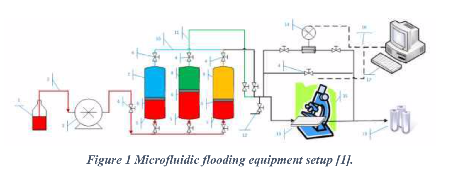
The constructed circuit is equipped with a programmable syringe pump (Chemyx® Fusion 100, Stafford, USA) and two pressure sensors (Elveflow®, Paris, France) as shown in Figure 1. The system follows a simple working principle. A control program designed using the graphical programming environment LabView (National Instruments® Austin, Texas) is used to monitor and ensure the correct functioning of the apparatus. The interface portrays the real time values of the pressure sensors and generates a scenario-representative graph. The nanofibrous scaffolds were secured inside the camera. This system allows the control of the flow and the measurement of the transmembrane pressure, enabling the study of the permeability characteristics of our HTM model. In our experiment, we first introduced the different electropsun meshes inside the camera and perfused them with a flow rate of 20 µL/min for 20 min. On forward steps, HTMC seeded on PCL scaffolds will be introduced in the camera with the same flow rate to observe pressure differences. For future lines, the effect of pressure on these cells will be studied and different drugs will be perfused to observe the cell´s response.
Published November 2020
Authors: Maria Bikuña Universidad de Navarra, E Carnero González, L Extramiana Esquisabel, Javier Aldazabal Tecnun – University of Navarra
Microfluidic setups are generally employed to investigate the fluid flow within microchannels. In our case, we are interested in observing colloidal particles(1-5 µm) under fluid flow with flow rates of the order of 5µl/min in a micron-sized channel. Apart from this, we are also looking to produce mono-dispersed micron-sized droplets using droplet forming chips which have the channel size of the order of 170µm. For smooth production of droplets, liquids of both continuous and discrete phases are needed to get injected into its channels with the typical flow rates of 5-50µl/min. For obtaining such flow rates with fewer oscillations and fluctuations, Chemyx Fusion 4000 multi-channel syringe pump has proven to be helpful.
Rahul Mangal
Assistant Professor
Department of Chemical Engineering
Indian Institute of Technology (IIT) Kanpur
Gradients generation and characterization inside microfluidic chip
For the generation of a stable gradient through the Matrigel core compartment, a source-sink mechanism was created, with a solution of FITC-labeled nanoparticles (0.5 mg/ml) in PBS perfused through one side channel, and PBS perfused through other using a Nexus 3000 syringe pump (Chemyx). Three-milliliter syringes were used to introduce PBS with or without the nanoparticles at a rate of 8 μl/hour. The experiment was performed under a Nikon Eclipse Ti-E fluorescence microscope (Nikon Instruments, Japan) for time-lapse imaging of the gradient formation.
Profile and stability of the dynamic gradient were analyzed using NIS-Elements AR (Nikon) software. The chips were analyzed at different time points between 0 and 12 hours with continuous perfusion. Built-in “plot profile” module was used for assessing the gradient intensity and stability over time. The intensity profile corresponds to distance versus intensity. A 3D projection was also reconstructed using software.
Study methods For the purpose of our research, we modified and upgraded the system for CCBD [11]. In the upgraded CCBD system, controllability over the process of dilatation is met on two levels: control over the maximum diameter of dilatation and control of the parameters of the dilatation process (i.e., pressure in the balloon extension, dilatation speed). These two levels of control are reached by using the Nexus 6000 Syringe Pump (Chemyx, Stafford, TX, USA) and our original software application that allows the dilatation process to operate under strictly controlled conditions (dilatation process lasted 100 seconds; pressure in the balloon extension did not exceed 2 MPa). The tracking and measurement of the dilatation parameters were performed by the pressure sensor, which is located on the dilatator device, as well as by the displacement sensor, which is attached to the hydrostatic pump, as shown in Fig. 1.

In our aim to precisely measure and basically map the resistance along the cervical canal during CCBD, we used the following pressure-sensitive films (PSFs): FUJIFILM Ultra Super Low Pressure (Fujifilm, Tokyo, Japan). Under the influence of external force on the PSF, microcapsules in component A of the film rupture and the released red paint is absorbed by the special material in component B, as shown in Fig. 2a. The width of the PSF used in our study was 3 mm and the length was 70 mm. Adhesive tape was placed at both ends of the PSF to keep components A and B together during the experiment. We also placed adhesive tape at the top ends of the PSF to avoid their movement during placement of the balloon extension in the cervical canal, as shown in Fig. 2b. Owing to the presence of cervical mucus and blood during the experiment, we had to isolate our PSF with transparent plastic foil. Finally, in every experiment, we used two PSFs, which were placed on the top and the bottom, respectively, of the balloon extension of the CCBD system.

After completion of dilatation, the PSFs were collected, scanned and converted into their respective digital forms, which were further analysed using the MATLAB program (MathWorks, Natick, MA, USA). The final versions of the processed PSFs are displayed in the Results section.
Microfluidic platform
Flow synthesis of Mn-doped CsPbCl3 QDs was carried out in an automated modular microfluidic platform previously developed in our group. The assembly of the microfluidic platform involves three structural core modules of the support structure, flow cell, and sampling tracks (custom machined in aluminum, Stratasys Direct Manufacturing). All the fluid-streaming components (tubing, fluidic connections, and fittings) were purchased from IDEX-Health & Sciences. An in-house LabVIEW script was utilized to centralize control of different modules of the automated microfluidic platform, including a dual syringe pump (Chemyx, Fusion 4,000), a mass flow controller (Bronkhorst, EL-FLOW Select), a 30 cm translational stage (Thorlabs, LTS300, with a maximum linear velocity of 5 cm s−1), a high-power LED (Thorlabs, M365LP1), fiber-coupled light source (Ocean Insight, DH-2000BAL), and a fiber-coupled photospectrometer (Ocean Insight, Ocean HDX Miniature Spectrometer).
In-flow cation doping of Pb halide PQDs
Continuous metal cation doping of CsPbCl3 QDs was carried out at room temperature in the modular microfluidic platform shown in Figure 2A. The washed CsPbCl3 QDs and MnCl2 precursor were loaded in gas-tight stainless steel (SS) syringes (Chemyx, 50 mL) under inert conditions. To achieve in-flow concentration tuning of the dopant precursor, the dopant solvent (ODE) with the same ligand-to-solvent ratio (OAm:ODE) was prepared and loaded in another SS syringe under inert conditions. Fluorinated ethylene propylene (FEP) tubing (0.02″ ID, 1/16″ OD) was utilized to connect the precursor syringes to off-the-shelf T-junctions and a custom-designed polyether ether ketone (PEEK) four-way junction. The FEP tubing (0.01″ ID, 1/16″ OD) was also used to fabricate two inline static micromixers with a dead volume of 2 μL for intensifying the microscale mixing efficiency of the chemical precursors.
The concentrated MnCl2 precursor and dilution solution streams were directed to an off-the-shelf T-junction and then passed through a braided micromixer to continuously adjust the concentration of the dopant precursor before the cation-doping process. Next, the diluted stream of MnCl2 and washed CsPbCl3 QDs were mixed in another in-series T-junction and braided micromixer to achieve a homogeneous reactive mixture before entering the modular microfluidic reactor. The pre-mixed cation-exchange reaction solution and the inert carrier fluids (i.e., Ar and PFO) were then directed to the modified PEEK cross-junction to form a three-phase flow throughout the flow reactor (FEP tubing, 1/16″ ID, 1/8″ OD). The in-flow cation-doping process was accurately and thoroughly monitored at different residence times along the flow reactor without changing the precursor flowrates (i.e., mixing timescale). The mobile three-port flowcell installed on the translational stage enabled monitoring of the fast cation-doping reaction through time-to-space transformation at 22 distinct optical ports. Concentrations of the dopant precursor and OAm were tuned on the fly by adjusting the volumetric flow rates of the washed CsPbCl3 QDs (Q1) and the diluted MnCl2 precursor (Q2 = Q2-1 + Q2-2; where Q2-1 and Q2-2 are the volumetric flow rates of the concentrated MnCl2 precursor and the dilution solution, respectively) to be Q1:Q2 = 1:1. To establish a stable three-phase flow at high axial flow velocity (Video S1) for reaction-limited kinetic and mechanistic studies of the cation-doping process, the flow rates of Ar and PFO streams were set at 5 and 1 mL/min, respectively. Mathematical correction factors were calculated and applied to ensure identical absorption and photoluminescence results for one unique sample across all optical monitoring ports along the flow reactor.
Read Full Article Here: Ultrafast cation doping of perovskite quantum dots in flow
Authors: Fazel Bateni 3 Robert W. Epps 3 Kameel Abdel-latif Tong Cai Ou Chen Milad Abolhasani
Published: May 25, 2021
Flow Equipment
The technical drawings for the prototype development of the static mixer were created using the AutoCAD software from Autodesk. The static mixer was 3D printed in stainless steel 1.4404 (316L/V4A) at the d3d Manufacturing GmbH (Baindt, Germany) using the selective laser melting (slm) process. Threads and sealing surfaces were machined afterwards. Steel capillaries with an outer diameter of 1/16″ and an inner diameter of 1.0 mm consisting of stainless steel 1.4404 (316L/V4A) were used, which were purchased from TECHLAB. PTFE tubing with an AD (1/4″) and ID (1/8″) was purchased from Bohlender and PEEK capillaries AD (1/16″) and ID (1.0 mm) from BGB and cut to the required lengths. All solutions were pumped with Fusion 4000 pumps from CHEMYX and high-pressure glass syringes from CETONI in volumes of 10, 25, 50 mL. Flow microreactor systems were dipped in individual bath to control the temperature. The syringe holders for the syringe pump were designed according to the requirements and 3D printed at JOMANTIK in Alumide.
General procedure A:
Continuous flow synthesis for the preparation of single homologated boronic esters All single homologations was carried out with the setup shown in scheme 3. The developed static mixer also represents the reactor with a volume of 60 µL. Stainless steel capillaries 1/16” (ID = 1 mm) were used for all connections. All solutions were pumped using Fusion 4000 pumps from CHEMYX. A precooled stream (coiled cooling loop VR = 1.00 mL, l = 127.4 cm) containing the boronate (0.1 M in THF, 14.72 mL/min, 1.00 eq.) and ClBrCH2 (1.50 eq.) was combined with a precooled stream (coiled cooling loop VR = 1.00 mL, l = 127.4 cm) containing Table 2: Residence time optimization of 1,2-aniotropic rearrangement. Yields determined via GC using internal standard. S-18 nBuLi (1.5 M in hexane, 1.28 mL/min, 1.30 eq.) in a static mixer. The mixture was reacted at – 40 °C for 225 ms (VR = 60 µL, V̇ total = 15.98 mL/min) before the stream was directed to an electrically heated water bath at 40 °C for 9 s (VR = 2.40 mL, l = 305.7 cm). To ensure that the system was in a steady state mode, the system was flushed for 30 s (approx. 6 reactor volumes) before sampling was started. The resulting stream was dropped into a saturated aqueous solution of NH4Cl and extracted with Et2O. The combined organic phases were washed with brine, dried over MgSO4, filtered and the solvents were removed under reduced pressure. The crude residue was purified by column chromatography (silica gel; pentane:Et2O 100:1) to yield the homologated boronates 5a-h.
Read the full article here: The Matteson reaction under flow conditions – iterative homologations of terpenes
Authors: Conrad Kuhwald and Andreas Kirschning* Institute of Organic Chemistry, Leibniz University Hannover, Schneiderberg 1B, 30167 Hannover, Germany
Nanoparticle as part of nanotechnology has already drawn attention to its great potential of enhancing oil recovery. In the last few years, some publications have already addressed this topic, but the basic enhanced oil recovery (EOR) mechanisms have not been released very clearly. A visualization flooding method (glass micromodel) will be used to investigate the EOR mechanisms of nanoparticle fluid in our lab in the future [1].
The developed microfluidic application is a powerful mimetic model for the real-time visualization of the chemical-based heavy oil recovery process in the micro/nanoscale. Considering the time-consuming and expensive nature of core flood experiments, this method provides an attractive alternative for rapid and low-cost chemical-enhanced oil recovery (EOR) screening studies [2].
A customized transparent glass micromodel will be utilized as porous media, and synthetic brine will be used to disperse nanoparticles. The effects of different kinds of nanoparticles and different nanoparticle concentrations on EOR will be investigated, and some properties between oil and water will be measured to uncover EOR mechanisms [1]
The Chemyx Fusion 6000 high-pressure syringe pump will be used in this equipment setup as the driving apparatus for injecting brine, nanofluid and crude oil into the micro-glass model. The reason for choosing Chemyx Fusion 6000 pump is the ultra-low flow rates it can
provide. The pore volume of a glass micromodel is extremely small in order to mimic the actual pore channels in rock e.g. sandstone or shale. Normally the flooding volume of a core-flooding experiment will be several pore volumes, so the flow rates required for this kind of experiment are strictly low and accurate. The injecting process will be recorded by a camera integrated into a microscope. We are building up the whole system and the Chemyx Fusion 6000 pump will be one of the most important parts.
Bibliography
[1] Shidong Li and Ole Torsæter. Norwegian University of Science and Technology. An Experimental Investigation of EOR Mechanisms for Nanoparticles Fluid in Glass Micromodel. International Symposium of the Society of Core Analysts held in Avignon, France, 8-11 September, 2014
[2] P. Bazazi, I. D. Gates, A. S. Nezhad, S. H. Hejazi. University of Calgary. Silica- Based Nanofluid Heavy Oil Recovery A Microfluidic Approach. SPE Canada HeavyOil Technical Conference, Alberta, Canada, 15-16 February, 2017.
Article By: Virginia Tech Lab
Preparation of Cation Doping Precursor
A 0.12 M Mn(Ac)2 precursor was prepared by dissolving 1245.8 mg Mn(Ac)2 powder, into 50 mL ODE, and 10 mL OA. The metal cation dopant precursor was heated under N2 at 150 °C for 2 h. A mixture of OA–ODE (1:2) was used to further dilute the dopant precursor in flow.
Modular Fluidic micro-processor
The modular flow synthesis platform was constructed using three main modules: 1) precursor delivery, 2) reaction, and 3) spectral monitoring modules. The process flow diagram is shown in Figure S7, Supporting Information. The precursor delivery module included nine automated syringe pumps (seven Chemyx Fusion 6000 and two Chemyx Fusion 4000 syringe pump) loaded with gas-tight stainless steel syringes (nine 50 mL, Chemyx) and one automated mass flow controller (MFC, Bronkhorst, EL-Flow Select) for the controlled injection of liquid precursors and Ar into the fluidic micro-processor. All the syringes and MFC were connected to the fluidic junctions by fluorinated ethylene propylene (FEP) tubing (500 μm inner diameter, ID, 1.59 mm outer diameter, OD, 90 cm long). Both fluidic micro-processors were constructed using 750 μm ID FEP tubing. The CsPbBr3, SnCl4, PFO, and Ar streams were directed to a custom-designed five-port segmentation module to form a three-phase flow in the first fluidic micro-processor. The pristine NC stream was formed by mixing a concentrated CsPbBr3 NCs solution (4 mM) with pure toluene in a T-junction before entering the segmentation module. The SnCl4 stream was formed by in-flow mixing of the SnCl4 precursors in a four-way cross-junction (IDEX Health & Sciences) with OAm–TOL (1:2), OA–TOL (1:2), and pure TOL streams. Two in-line braided tubing were used to ensure uniform mixing of the CsPbBr3 and SnCl4 streams before entering the segmentation module. The Mn(Ac)2 stream was formed by in-flow mixing of the Mn(Ac)2 precursor with the OA–ODE (1:2) and pure ODE streams. The in-line injection of the metal cation doping precursor into the reactive phase droplet exiting micro-processor 1, before entering micro-processor 2, was accomplished through a T-junction. The total flow rates of the precursors in micro-processor 1, micro-processor 2, PFO, and Ar were set at 400, 250, 50, and 500 μL min−1, respectively. The spectral monitoring module consisted of two custom-machined flow cells, located at the end of each fluidic micro-processor for in situ PL spectroscopy of the in-flow doped LHP NCs. Each flow cell was connected to a fiber-coupled UV LED (365 nm, Thorlabs, M365LP1) as the only excitation light source, and a fiber-coupled spectrometer (Ocean Insight, Ocean HDX Miniature Spectrometer) in a 90° configuration. The in situ PL spectra were acquired using an integration time of 20 ms. To reduce the signal-to-noise ratio for the PL spectroscopy after cation doping reaction, the outlet of micro-processor 2 was connected to an adapter (IDEX union) to increase the FEP tubing ID to 1.59 mm (3.18 mm OD). The droplet formation stability and uniformity within the three-phase flow configuration in both microreactors were studied using the methodology reported in our previous work.[41] The travel time of each phase passing through the flow cell was measured by monitoring the PL intensity at 400 nm in each flow cell.
Read Full Article Here: Autonomous Nanocrystal Doping by Self-Driving Fluidic Micro-Processors
Authors: Fazel Bateni,Robert W. Epps,Kameel Antami,Rokas Dargis,Jeffery A. Bennett,Kristofer G. Reyes,Milad Abolhasani.Published
Date: 13 March 2022
Experimental Setup (Microscale). Microfluidic continuous flow reactors consisted in stainless steel (SS) coils (1.58 mm o.d. x 500 μm i.d.) equipped with SS nuts, ferrules and unions (VALCO). In experiments involving crude glycerol, the reactor consisted in a SS coil (3 mm o.d. x 2.1 mm i.d.) equipped with reducing unions (1/8” to 1/16”, Swagelok). The reactors were thermoregulated with a HeidolphTM MR Hei-Tec® oil bath equipped with a Pt-1000 temperature sensor. Sections of the reactors that were not subjected to high temperatures were constructed from PEEK or PFA tubings (1.58 mm o.d. x 750 μm i.d.) equipped with PEEK/ETFE connectors and ferrules (IDEX/Upchurch Scientific). Feed solutions were handled with high force Chemyx Fusion 6000 syringe pumps equipped with SS syringes and Dupont Kalrez O-rings or with Knauer Azura P 4.1S HPLC pumps. Downstream pressure was regulated using a dome-type back pressure regulator (Zaiput Flow Technologies BPR-10) connected to a nitrogen cylinder to set the working pressure (11 bar). In-line NMR reaction monitoring was carried out using a 43 MHz Spinsolve™ carbon NMR spectrometer from Magritek® .
Read Full Article Here: Versatile and scalable synthesis of cyclic organic carbonates under organocatalytic continuous flow conditions
By: Romaric Gérardy, Julien Estager, Patricia Luis, Damien P. Debecker, and Jean-Christophe M. Monbaliu.
Published On: January 2021
Mud Injection
Mud injection test was carried out by entering the prepared mud slurry into the syringe of a Nexus 6000 syringe pump system (Chemyx, USA).The fluid penetration test at 1 ml/h injection rates lasted for 30 minutes. As seen in figure 3, B5N0.75PAC had minimum filtrate penetration into the micromodel. Obviously, lower filtrate penetration depths will be associated with less formation damage. The base mud (B5) caused maximum formation damage during the very first minutes and the filtrate penetrated deeply into the porous media. Bulletin de la Société Royale des Sciences de Liège, Vol. 86, special edition, 2017, p. 201 – 205
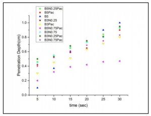
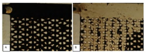
Figure 4 shows the wellbore of the main channel when the cake had not yet formed. Consequently, almost all oil is driven out of the formation. This figure indicates the necessity of creating the filter cake to decrease fluid loss. The following figure depicts the injection of B3N0.25 into the micromodel. As mentioned earlier, low concentration nanoclays are highly lubricating and they can reduce the level of viscosity.
Conclusions
Comparison between mud samples with and without nanoclay revealed that at high shear rates, adding nanoclay improved the reduction in viscosity by up to two times. According to dynamic tests, the penetration depth of the formulation containing nanoclay and PAC (B5N0.75PAC )was about 1.5 times less than that of the base mud.
Acknowledgment
The authors would like to thank the IKIU nano-tech unit and micromodel laboratory of institute of petroleum Engineering of Tehran University for their financial and technical supports
Read Full Article Here: Evaluation of PAC with Nanoclay as drilling mud
sEV CAPTURE FROM PLASMA
Normal Flow Filtration:
Small extracellular vesicle experiments were performed using purified human plasma (Equitech-Bio, Inc., Kerrville, TX). NFF experiments were performed using NPN chips with 50 nm thick freestanding membranes, with an average pore diameter of 50 nm and a porosity of 15% in a SepCon™ centrifuge cup (SiMPore Inc., Rochester, NY). A 500 μL sample of undiluted plasma was spun at 1500 x g through the membrane and the chip was extracted from the device. The chip was allowed to dry and was then imaged by scanning electron microscopy as described below.
Tangential Flow for Analyte Capture:
Nanoporous silicon nitride microfluidic devices were fabricated as described above. The NPN chip used had a 50 nm thick freestanding membrane with a 50 nm average pore diameter and a 15% porosity. 1 mL of plasma was passed tangentially to the membrane surface at a rate of 10 μL/min using a syringe pump (Chemyx Fusion 200 Syringe Pump, Chemyx Inc., Stafford, TX), while fluid was actively pulled through the membrane at a rate of 2 μL/min. After processing the full 1 mL volume, the device was unclamped and the chip extracted. Captured sEVs were labeled for CD63 (Abcam, Cambridge, MA) and imaged via scanning electron microscopy as outlined below.
Capture and Release
Microscale Experiments:
Flow experiments were performed using two Chemyx Fusion 200 syringe pumps (Chemyx Inc., Stafford, TX). Micron scale experiments with 10 μm polystyrene green fluorescent particles (Thermo Scientific, USA) were conducted on 8 μm track-etch membranes. The capturing step was performed using a sample supply flow rate of 90 μL/min and an ultrafiltration/pulling rate of 10 μL/min. Captured particles were released by a reversed flow of 10 μL/min through the membrane.
Nanoscale Experiments:
These experiments were conducted using 100 nm polystyrene green fluorescent particles (Thermo Scientific, USA) on PCTE or NPN membranes with 80 nm median pore size. Nanoparticles were captured by a supply flow rate of 5 μL/min and the ultrafiltration/pulling flow rate of 2 μL/min. The input channel was then cleaned by rinsing buffer to wash away the floating particles under the same flow condition as the capturing step. Finally, captured particles were released by a reversed flow of 2 μL/min through the membranes.
EXPERIMENT: Millipore water (18.1 Ω) was used for all experiments. NaCl(s) (Sigma-Aldrich; 99.9% purity) and CO2(g) (Praxair; 99.999% purity) were used as received. Fluidic System. Figure 1A shows a simplified diagram of the experimental setup that was designed to generate concentration profiles of CO2 in water (or in brines) as a function of time at 90 ± 2 bar and 50 ± 2 °C.

The fluid handling system consists of two Teledyne ISCO model 100DM pumps (pumps A and B), two Chemyx Nexus 6000 syringe pumps (pumps C and D), and stainless steel and PEEK tubing and valves to deliver and control the flow pattern at high pressure and temperature. A homemade right-angle PEEK holder (Figure 1B) connects fused silica capillaries (Polymicro Technologies; 150 or 200 μm diameter) to the fluidic system. The entire fluidic setup, with the exception of the pumps, is kept in an insulated box in which the temperature was controlled with an active PID controller (Omega Engineering, model CN8DPt)) within ±2 °C. In a typical experiment, the fluidic pathway is thoroughly flushed (to remove air in the system) and filled with water (or brines) among valves V1, V2, and V3 with pump A. Thereafter, with valve V2 closed, pumps B and C are synchronized in a “push− pull” motion to deliver and withdraw scCO2 to and from the system. This process replaces water (or brine) between V1 and V3 with scCO2 (the flow path indicated in yellow in Figure 1B) while leaving a trapped stationary water/brine column in the capillary tubing from point A to V2 (blue line). This procedure establishes a stable aqueous/scCO2 interface at point A (x = 0) in the PEEK adapter.
Confocal microscopic imaging
Images of the flow fields in the microfluidic channels were acquired on a laser-scanning confocal microscope (Nikon A1Rsi, Nikon Instruments Inc.). The wavelengths of the lasers used to excite the red and green fluorescence were 561 and 488 nm, respectively. The two molecules, dextran-RB and dextran-FITC, were dissolved in DI water at a concentration of 0.1 mM and injected into the mixers with a two-channel microfluidic syringe pump (Model Fusion 100CR, Chemyx Inc.). Fluorescence images of red and green channels were taken after the flow reached a steady state with an exposure time of 2.1 s. The two-color channels were combined with ImageJ (1.52r; National Institutes of Health, USA), with which the quantitative intensity of the red channel was also measured.
Fabrication and characterization of microfluidic-integrated salinity sensor
The salinity sensors were fabricated on 500-μm-thick wafers that have an oxide layer of 300 nm (University Wafer Inc.). Electrodes (10/190 nm Cr/Au, line width of 100 μm, 60 μm separation within one channel) and alignment marks were deposited via standard photolithography procedures in the cleanroom. Before printing microfluidic structures, the sensor chips were cleaned by submerging in acetone, methanol, and isopropanol for 3 hours each, rinsing with DI water, and blowing dry with high-purity N2. During printing, the alignment marks were used to align the sensor chips with the coordinate system of the printer. The completed salinity sensors were housed in a multielectrode chip platform (ED-ME-CELL, MicruX Technologies), which was connected to a mini USB box via an insulation-displacement contact cable, allowing each channel to be individually addressed. The impedance measurement of DI water and NaCl solutions was conducted on a semiconductor device analyzer (B1500A, Keysight Technologies Inc.) as the sensor was flushed at a flow rate of 50 μl/min via a two-channel syringe pump (Model Fusion 100CR, Chemyx Inc.). Real-time measurement of solution impedance was conducted at a frequency of 60 kHz.
2.2 Voltage Conversion
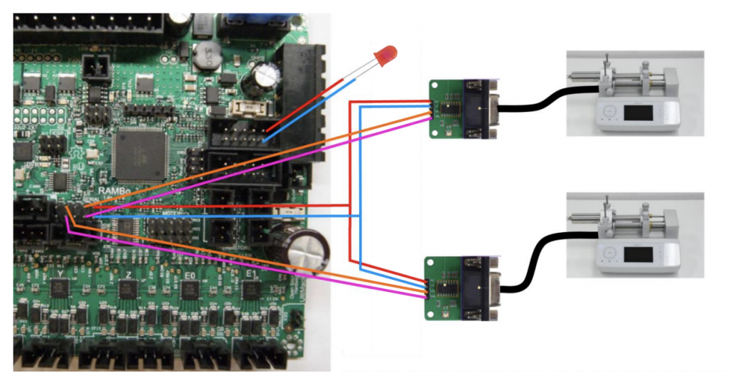
The RAMBo has four rows of pins used to send and receive UART serial commands. However, the serial port on the Fusion 6000 syringe pump is an RS232, which sends and receives signals at a different voltage level than the RAMBo. To solve this problem, two RS232 to TTL converters are used (BC71075, NKC Electronics). The converters, shown in Figure 2, are built around a MAX232 chip, which uses a capacitive voltage generator to transform the 5V signal from the RAMBo into a 15V signal that the RS232 port can recognize [4]. A more detailed schematic of the converters can be found in Figure A3 in the appendix.
These two converters connect two of the four rows of serial pins in the RAMBo to the two extruders. Hypothetically, if one were to add more extruders for builds that required additional printing materials, a third and fourth extruder could be added by purchasing two additional converters and using the remaining two serial pins.
By the Department of Industrial and Enterprise Systems Engineering
2.2 Experimental Apparatus
A schematic of the reactor setup is shown in Fig. 2. Two Chemyx Nexus 3000 syringe pumps (Stafford, TX) syringe pumps were used along with 10 mL glass gas-tight syringes (SGE, Victoria, Australia) to pump reagents M4MAA (1) and DMF-DMA (2) to the tee junction and through the reactor coil respectively. The tubing reactors used in the flow experiments were constructed using 1.59 mm outer diameter (OD) PTFE tubing with either a 1.0 mm or 0.25 mm inner diameter (ID), polyetheretherketone (PEEK) tee junctions, and were assembled using suitable nuts and ferrules (IDEX Health and Science). The polytetrafluorethylene (PTFE) reactor coil was immersed in a water bath that was pre-heated or pre-cooled to the desired reaction temperatures.
1 Continuous-flow setups 1.1 Generalities 1.1.1 Pumps Chemyx Nexus 3000 and Chemyx Nexus 6000 syringe pumps were used to handle the feed solutions of tetrabutylammonium azide (nBu4NN3), tosyl chloride (TsCl), p-toluenesulfonyl azide (TsN3), methyl phenylacetate (2a) and 1,8-diazabicyclo[5.4.0]undec-7-ene (DBU) in NMP, methyl phenyldiazoacetate (4a), N-Boc piperidine (3a) and Rhodium(II) octanoate dimer (Rh2(oct)4) in hexane, 4-methyl-N’-(2-oxo-1-phenyl-2-(piperidin-1-yl)ethylidene)benzene sulfono-hydrazide (3b), DBU and Aliquat® 336 in toluene and HCl in ether/methanol or dioxane/methanol. The feed solutions were loaded in Chemyx® stainless steel 5 or 20 mL syringes equipped with DupontTM Kalrez® SpectrumTM AS-568 o-rings (0.239 x 0.070” or 0.549 x 0.103”).
ThalesNano® micro HPLC pumps (0.01 – 10 mL min-1 , max 80 bar, wetted parts: SS 316, ruby and sapphire) were utilized to inject the extraction solvents (10 wt% and 15 wt% aqueous sodium chloride and hexane) and the feed solutions of 4-methyl-N’-(2-oxo-1- phenyl-2-(piperidin-1-yl)ethylidene)benzene sulfonohydrazide (3b), DBU and Aliquat® 336 in toluene for the mesoscale experiments (Corning® Advanced-FlowTM Low-Flow reactor).
A FUJI TechnologiesTM pump (triplex plunger pump HYM-08) was utilized to handle the feed solutions of 4-methyl-N’-(2-oxo-1-phenyl-2-(piperidin-1-yl)ethylidene)benzene sulfonohydrazide (3b), DBU and Aliquat® 336 in toluene for the mesoscale experiments (Corning® Advanced-FlowTM G1 reactor).
1. Plug in and turn on Automated Lateral Flow Reagent Dispenser (ALFRD) unit and external syringe pump.
2. Program syringe pump flow rate according to manufacturer’s instructions. a. See Figures 2 and 3 in Appendix A for recommended flow rates. b. ClaremontBio recommends using the Chemyx Fusion 200 Syringe Pump.
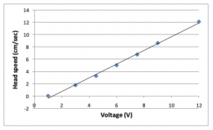
3. Select voltage on power supply. A range of 4.5 – 6V is recommended. a. If a faster head speed is desired, a power supply can connected in lieu of the provided power supply; however, 12V is the maximum voltage that can be used for the ALFRD.
4. Secure dispense tips into desired placement slot on dispense tip head using provided Allen wrench.
a. For best results, position tips very close to the membrane surface, without direct contact (unless contact is desired). i. Actual height is dependent on membrane type and thickness. -2 0 2 4 6 8 1 0 1 2 1 4 0 2 4 6 8 1 0 1 2 Head speed (cm/sec) Voltage (V) ALFRD v5.2 3 Rev. 03/10/2019
b. Tips positioned too high may result in liquid droplet formation or uneven lines.
c. To test positioning, place membrane on dispense table and initiate switch to cause table to move. Drag on membrane will be apparent. i. Once desired height is established, it may be helpful to mark position on metal post of dispense tip with a permanent marker.
5. Once dispense reagents have been prepared, remove air bubbles prior to use in ALFRD (i.e. quick centrifugation, nitrogen air purge).
a. A volume of 200 µl or greater is recommended.
b. When solution is running out during dispensing, lines will appear thinner and may produce varying results. 6. Draw up each solution into a syringe, taking care to minimize air bubbles.
7. Attach tubing to blunt syringe needle and secure filled syringes on syringe pump according to manufacturer’s instructions.
8. Turn on syringe pump to prime solution(s) through tubing and dispense. Turn off pump and wipe away residual liquid.
9. Secure membrane onto ALFRD dispense table using magnets.
10. Turn on syringe pump, followed immediately by dispense table switch.
11. Once dispense tips have reached the end of the table and stopped, turn off syringe pump.
12. Remove membrane from table.
13. Return dispense tips to their original position by reversing the table switch.
14. Wipe off any residual liquid from table.
15. Repeat for each membrane as necessary.
A stock solution was prepared by suspending TiO2 nanoparticles (Titanium oxide, anatase, less than25 nm, 637253-50G, Sigma-Aldrich) in a solution of 4-(trifluoromethyl)benzyl alcohol (SC034058, Fluorochem Limited) in acetonitrile (MeCN, HPLC-R, Biosolve Chimie SARL). For the exact concentrations, we refer to the corresponding experiments (see section 3.2). The TiO2 particles were smaller than 25 nm, which is, however, the initial size of these particles. The actual powder consists of aggregates and agglomerations of these primary particles. The actual particle size distribution of TiO2 particles in the solution was measured by a laser particle sizer (Analysette 22 microtec plus, Fritsch). As shown in Fig. S1 (See Supporting Information), the measured size distribution shows a wide distribution with three agglomeration peaks, falling in the range of 0.1–1, 1–10 and 10–40 µm respectively. The average size is 3.8 µm. Next, the stock solution was taken up in a 60 mL plastic syringe, in which a magnetic stir bar was placed. The syringe was mounted on a syringe pump (Fusion 720 Fusion 200, Chemyx Inc.).
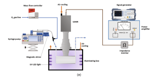
Magnetic stirring was applied by putting a compact magnetic stirrer (Topolino, IKA) beneath the front part of the syringe (as shown in Fig. 2). In this way a uniform suspension was maintained inside the syringe and could reliably be introduced into the ultrasonic milli-reactor. To prevent particles settling down at the inlet microfluidic connections, these connections were kept as short as possible (ca. 5 cm) and were placed in a downward trajectory before reaching the reactor. The gas phase was fed from an oxygen gas line and dosed into the liquid stream using a mass flow controller (F-200CV-002-AAD-22-K, Bronkhorst Nederland BV). The gas and liquid phase were combined in a stainless-steel tee junction (VALCO) to establish a gas–liquid Taylor flow regime and were subsequently delivered to the photochemical ultrasonic milli-reactor. Therefore, a gas–liquid-solid three phases flow was formed in the millichannel, which was exposed to the UV light. The physical properties of the three phases are listed in Table 1.
Date Published: June 2021
Read the full article here: A mesoscale ultrasonic milli-reactor enables gas-liquid-solid photocatalytic reactions in flow
Authors: Zhengya Dong Zhengya Dong, Stefan D. A. Zondag Matthias, Schmid Zhenghui Wen (University of Amsterdam), Timothy Noel Eindhoven (University of Technology).
Bonding quality test. Inertial devices are operated at high flow rates; hence, the bonding technique must provide enough strength to prevent leakage from the interface. To evaluate the bonding quality of our proposed technique, a simple 3D-printed straight channel featuring 50 µm height, 200 µm width, and 4 cm length was bonded to a 2-mm-thick PMMA layer. A high-pressure syringe pump (Chemyx Fusion 4000 Syringe Pump, Chemyx, TX, USA) was used to inject fluids inside the channel from a small syringe (6ml). Increasing the flow rate leads to the generation of Safman-Taylor fngers around the inlet, in which the most pressure in the channel present (Section S2). Safman-Taylor fngers are generated by the movement of a viscous fluid within a porous material75,76. As the bonded adhesive tape forms a porous zone between the connecting parts, this theory is applicable for the bonding evaluation. An increase in the applied pressure leads to developments of the Safman-Taylor fngers until the bonding fails. A CCD camera (DP80, Olympus, Tokyo, Japan) mounted on an inverted microscope (IX73, Olympus, Tokyo, Japan) was used for monitoring the bonding integrity. All recorded data were obtained immediately after the bonding of the 3D-printed channels to a PMMA sheet.
Read the full article here: 3D Printing of Inertial Microfluidic Devices By Nature Science Reports Authors: Sajad Razavi Bazaz 2020 School of Biomedical Engineering, University of Technology Sydney, Sydney, NSW, 2007, Australia.
Operation of Nexus 3000 Syringe Pump
The operation of the syringe pump is straightforward and self-explanatory. Nevertheless, the different steps are quickly described.
1. First install the syringe on the pump after the syringe is properly filled with water and connected to the facility.
2. On the front panel, choose “Basic” (1 syringe) and press “Enter”
3. Set the syringe diameter (mm), the volume to be dispensed (ml) and the flow rate (ml/min). The operation direction is «Infusion».
4. Fill the syringe and bring the plunger of the syringe pump into position. Use the buttons F1 «Fast Forward», F2 «Forward», F3 «Reverse» and F4 «Fast Reserve». Play with the buttons prior of mounting any syringe as the direction is reversed due to the way we use the syringe pump. Otherwise in the worst case, you might break a syringe.
5. If the syringe is ready to be used, press «Start». You will get the following information displayed.
6. To stop the delivery you can press «Stop» or if the delivery is finished press «Stop» to enter the setup menu.
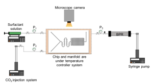
Microfluidic testing. Figure 2 shows the microfluidic chip design used to screen various supercritical CO2 (Sc-CO2) surfactant foams at different conditions. Te chip has one inlet connected to the surfactant solution and another to the CO2 injection system. An on-chip foam generator comprising a series of off-centered circular mixing channels was designed to produce consistent and uniform Sc-CO2 foams. The relative centers of the circular mixing channel walls of 0.5 mm inner diameter and 1.0 mm outer diameter were radially displaced by 0.05–0.1 mm. Te foam generator channel dimensions are 200 µm (width)×10 µm (depth).
The porous medium of the microfluidic chip is a homogeneous hexagonal channel network where the foam behavior at the pore-scale level of the reservoir rock is replicated and studied. The porous medium has pore dimensions of 30 µm (width)×10 µm (depth), correlating to a hydraulic radius of 15 µm. The pattern was transferred onto a silicon substrate and etched to the specified dimensions using reactive ion etching (RIE). To complete the fabrication, the RIE-etched silicon substrate was anodically bonded to a glass slide to seal of the analog from the atmosphere, provide a viewing window, and sustain microchannel pressures >13.8 MPa. Figure 3 shows the schematic of the experimental setup used to conduct the microfluidic testing. A new microfluidic chip was used for each test to ensure that the initial chip condition was the same for all experiments.
The microfluidic chip was mounted onto an in-house designed high-temperature high-pressure manifold and connected to the external experimental system: a syringe pump for surfactant injection (Chemyx Fusion 6000), two pumps for CO2 injection, and back-pressure regulation of the chip outlet pressure, respectively (Teledyne ISCO 260D), and external high-accuracy pressure gauges (Omega Engineering PX409-3.5KGUSBH). Foam testing was performed at 100 °C, and the back-pressure regulator was maintained at 13.8 MPa during foam injection for all microfluidic experiments to maintain CO2 at supercritical conditions. In addition, the entire fluid injection lines from pumps into the microfluidic device were insulated and maintained at the test temperature using a temperature controller (Omega Engineering CNi3222). The pump used to inject the CO2 was kept at the test temperature using a temperature-controlled mineral oil bath circulator and an insulation sleeve. It is also The pump used to inject the CO2 was kept at the test temperature using a temperature-controlled mineral oil bath circulator and an insulation sleeve. It is also noted that due to the high thermal conductivity of the silicon material, the thermal equilibration of fluids occurs quickly and effectively inside the microfluidic chip.
Published by Scientific Reports | (2021)
By AyratGizzatov, Scott Pierobon, ZuhairAlYousef, Guoqing Jian1, Xingyu Fan, AliAbedini & Amr I.Abdel Fattah
This experiment is used to understand the effects of physiological shear stress present in human fallopian tube on the cellular transformation and dissemination of malignant fallopian tube cells using Chemyx Fusion 6000 Syringe Pump.
Description:
The Chemyx Fusion 6000 syringe pump is used to pump viscous fluid consisting of methylcellulose and DMEM F12 (1:1) through a flow chamber to apply shear stress to healthy fallopian tube epithelial cells. The pump is set at a constant flow rate for 24 hours to pump viscous fluids that range from 0.007 to 2.06 Dyne/cm2.
From the tube to the ovaries: the role of shear stress on the origin of ovarian cancer
University of Michigan
Raneem Ahmad, Geeta Mehta

Contact our support team about Chemyx Syringe Pump products & services. We have experienced engineers to help you choose the right syringe pump product for your application!
CONTACT