Syringes pump systems are designed for delivering precise volumes and flow rates. Most commercial syringe pumps are built with CNC precision-machined components due to the extremely precise flow and volume accuracy requirements of various scientific applications.
Design
Syringe pump design features 3 main components comprising:
- Hardware (machined holders and lead screw)
- Motor (and drive electronics)
- Software (UI and I/O)
Hardware
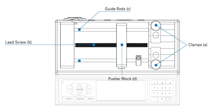
- Syringes of different sizes are held securely in place by adjustable syringe clamps(a). The lead screw(b) and guide rods(c) moves the pusher block(d) to initiate infusion. Learn more about the syringe pump parts and hardware components.
- Syringe pump parts and infusion pump parts are typically lubricated with carbon or lithium grease. Learn more about lubrication requirements.
Electronics
All positive displacement syringe pumps are driven by a stepper motor connected to the lead screw that allows for controlled angular movement. Further development of micro-electronics have allowed for RS232 cable control and USB cable control.
Modern syringe pump design typically includes an LCD touch screen controller as the primary input output device.
Secondary input output control can utilize RS232 or USB controls. Learn more about connecting the syringe pump for computer control.
Software
RS232 and USB connectivity allow for control from various commercial automation programs like LabVIEW and MATLAB. This allows pumps to work in tandem with a wide range of lab equipment, most of which have different control requirements. Learn more about connecting a syringe pump via USB or RS232.